How to Connect a DC Motor?
how to test a dc motor? The Following Tutorial Covers All Necessary Components and Is Suitable for Most DC Motor Applications.
I. Identify Core Components and Their Functions
- DC Motor: The core actuator that converts electrical energy into mechanical energy. It has two terminals (or leads) that need to be correctly identified as positive and negative (refer to the manual; typically red for positive and black for negative).
- Battery: Provides DC power, with the voltage needing to match the motor’s rated voltage (e.g., a 12V motor requires a 12V lithium battery). The capacity should be chosen based on the motor’s power consumption to avoid insufficient runtime.
- Controller (or Speed Controller): Used to regulate motor speed and control start/stop functions. Some models include forward/reverse capabilities (e.g., PWM controllers). The input connects to the power source, while the output connects to the motor.
- ESC (Electronic Speed Controller): Commonly used with brushless DC motors or high-current brushed motors. It functions similarly to a speed controller but can handle higher currents and receives control signals (such as from a remote control).
II. Preparations Before Connecting
- Check Component Parameters: Ensure that the battery voltage equals the motor’s rated voltage and matches the input voltage of the controller/ESC (e.g., all three being 24V) to prevent damage from voltage mismatches.
- Tools Preparation: Screwdriver, insulated wires (select specifications based on current, e.g., 16AWG wire for a 10A motor), terminal connectors (such as XT60 plugs for easy disassembly).
III. Complete Connection Steps by Scenario
Scenario 1: Brushed DC Motor (with Battery + Speed Controller)
Suitable for small devices (e.g., toy cars, small conveyors):
- Connecting Battery to Speed Controller: The speed controller has “+” and “-” terminals. Connect the battery’s positive lead (red wire) to the “+” terminal and the negative lead (black wire) to the “-” terminal (if using plugs, connect the battery plug to the speed controller input plug first, ensuring correct polarity).
- Connecting Speed Controller to Motor: The speed controller has “Motor +” and “Motor -” terminals. Connect the motor’s positive lead to “Motor +” and the negative lead to “Motor -“.
- Testing Basic Functionality: Turn on the speed controller switch, rotate the speed knob, and the motor should accelerate/decelerate accordingly. Turning off the switch stops the motor, indicating a correct connection.
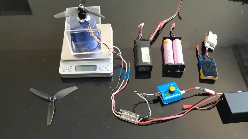
Scenario 2: Brushless DC Motor (with Battery + ESC)
Suitable for high-speed/heavy-load devices (e.g., drones, robots):
- Connecting Battery to ESC: The ESC input usually has an XT60 plug, which directly inserts into the battery’s XT60 socket (polarity is fixed via the plug, requiring no manual wiring).
- Connecting ESC to Motor: Brushless motors have three phase wires (typically yellow, blue, green). The ESC output has corresponding colored wires; connect them according to color. If rotation direction is incorrect, swap any two wires.
- Connecting ESC to Controller (e.g., RC Receiver): The ESC has a signal wire (with a plug) that connects to the “motor control channel” (e.g., CH3 on an RC receiver) to receive speed control signals.
IV. Key Considerations
- Correct Polarity: Incorrect polarity between the battery and controller/ESC will destroy components. Always verify interface labels (“+” to “+”, “-” to “-“).
- Current Matching: The ESC/speed controller’s rated current must be ≥ the motor’s maximum operating current (e.g., if the motor’s peak current is 15A, choose a 20A ESC) to prevent overload.
- Insulation Protection: After connecting, wrap exposed terminals with insulating tape to prevent short circuits. Solder joints at wire connections ensure secure contacts (loose connections cause overheating and unstable speeds).
V. Debugging and Verification
- Before First Power-On: Disconnect the motor output and test if the controller/ESC operates normally (power-on indicator lights up, and adjusting the knob shows signal output).
- Light Load Test: Connect the motor and run it at low speed for 30 seconds. Check for overheating (normal temperature ≤ 60°C); if no issues, gradually increase speed.
- Function Validation: Test start/stop, speed adjustment, and forward/reverse (if supported). If there are glitches or unusual noises, immediately disconnect power and check connections or phase errors.
By following these steps, you can achieve a complete connection between the DC motor, battery, controller, ESC, and other components. The core principles are “voltage matching, correct polarity, adequate current handling.” For scenarios like heavy loads or remote control, additional components such as fuses (for short-circuit protection) and signal amplifiers can further enhance stability.