26
Jul
What is brushless dc motor?
What is a Brushless DC Motor (BLDC)?
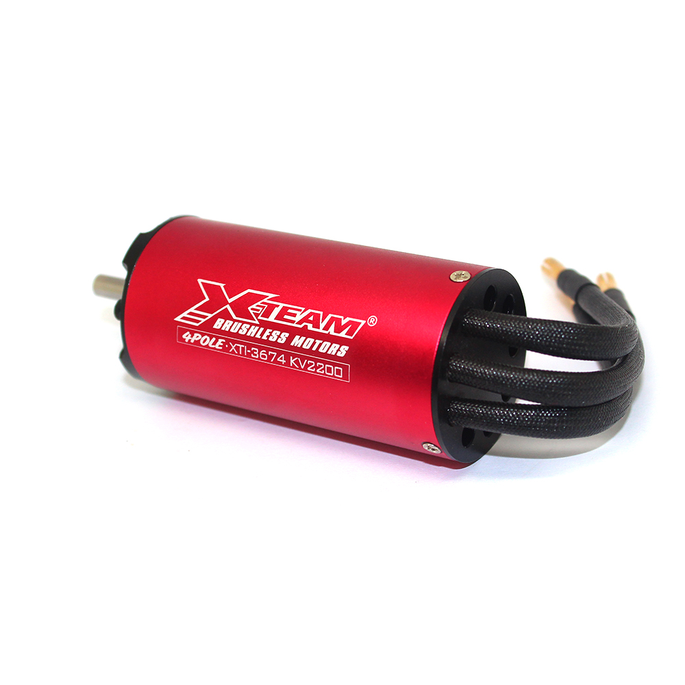
A Brushless DC Motor (BLDC) is a type of DC motor that uses electronic commutation instead of traditional mechanical brushes for commutation. It belongs to the category of synchronous motors. Thanks to its advantages such as no brush wear, low noise, and high efficiency, it is widely used in drones, electric vehicles, home appliances, and other fields. Below, we will analyze in detail from two aspects: structural composition and operational control circuit.

I. Structural Composition of Brushless Motors
The core of a brushless motor is “brushless + electronic commutation,” with its structure mainly consisting of three major parts: stator, rotor, and position sensor, as detailed below:
- Stator (Fixed Part)
- Function: To generate a rotating magnetic field to drive the rotor.
- Structure: Made up of laminated silicon steel sheets forming the core + armature windings (mostly connected in star or delta configurations). Windings are distributed in slots on the stator according to certain patterns (such as full pitch or short pitch), generating a magnetic field interacting with the rotor’s permanent magnets when energized.
- Features: Windings are directly connected to an external power source, with electronic switches controlling the sequence of energization (replacing the mechanical commutation of brushes).
- Rotor (Rotating Part)
- Function: To provide a constant magnetic field, interacting with the stator’s rotating magnetic field to produce torque.
- Structure: Composed of permanent magnets (e.g., neodymium iron boron, ferrite) and magnetic materials (e.g., silicon steel sheets). The permanent magnets are usually surface-mounted (SPM) or embedded (IPM) on the rotor core, forming alternating N/S poles.
- Features: The performance of permanent magnets (residual magnetism, coercivity) directly affects the motor’s power density and efficiency.
- Position Sensor (Key Auxiliary Component)
- Function: To detect the rotor position in real-time, providing a basis for the control circuit to switch the energization sequence of the stator windings.
- Types:
- Hall Sensors: Most common (low cost), detecting changes in the rotor’s magnetic field to output square wave signals (one signal every 60° electrical angle) to determine the rotor’s position interval.
- Encoders (Optical/Magnetic): Higher precision (e.g., 1024-line encoder), outputting quadrature pulse signals (A/B phases) for precise calculation of rotor angle and speed.
- Sensorless Technology: Estimates rotor position by detecting back EMF in the stator windings, suitable for cost-sensitive or space-constrained applications (e.g., small-power motors).
II. Detailed Explanation of Operational Control Circuit
The operation of a brushless motor relies on a control circuit to achieve closed-loop control from “position detection → logical judgment → power driving.” This circuit primarily consists of the following modules:
- Position Detection Circuit
- Role: Converts signals from position sensors (e.g., high/low levels from Hall sensors, pulses from encoders) into signals recognizable by the controller (digital or analog).
- Control Logic Unit (Core)
- Hardware: Typically a microcontroller (MCU, e.g., STM32) or digital signal processor (DSP), integrated with PWM generators, ADCs, etc.
- Software: Runs control algorithms (e.g., square wave control, sinusoidal control), generating driving commands based on position signals (e.g., which two phases of windings should be energized and at what duty cycle).
- Power Drive Circuit
- Role: Amplifies low-level signals (e.g., 3.3V/5V PWM) output by the control logic unit into high-voltage, high-current signals to drive the stator windings.
- Core Components: Three-phase bridge inverter (comprising six power switching devices, commonly MOSFETs or IGBTs). Each phase leg includes an upper switch (connected to the positive terminal of the power supply) and a lower switch (connected to the negative terminal). By controlling the on/off state of these switches (e.g., turning on the upper switch of Phase A and the lower switch of Phase B), the winding can be energized.
- Protection Circuit (Safety Assurance)
- Overcurrent Protection: Detects winding current via sampling resistors; if it exceeds the threshold, all switches are turned off (to prevent damage).
- Overvoltage/Undervoltage Protection: Monitors power supply voltage; triggers alarms or shutdowns in case of abnormalities.
- Overtemperature Protection: Uses temperature sensors (e.g., NTC) to monitor temperatures of power transistors or the motor; reduces power operation if overheating occurs.
By using “electronic commutation,” brushless motors have completely solved the problems of brush wear and spark interference in traditional brushed motors. Combined with modern control algorithms (such as Field-Oriented Control, FOC), their performance far surpasses early products, making them the preferred solution for efficient drives.